OpenWrt Router + Local VLANs + Guest Wifi
|
by Craig Miller
In this session, we will cover creation of VLANs on your OpenWrt router to create a DMZ. Additionally, we will create a Guest Wifi network. It will feel like a lot of steps, and it kind of is. But the beauty of OpenWrt is that it gives you the control to create the networks you can imagine, and solving real-world networking problems.
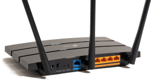
We'll be using a standard five (5) port home router running OpenWrt (v 23.05.5). While it possible to run the lab on a router with fewer ports, you will find that you will 1) run out of ports or 2) have to scale back what you configure on the ports.
VLANs solving problems
VLANs are for more than just connecting a single LAN port to a managed switch, to expand the number of available ports (as we did last time with the NanoPi).
We can also use VLANs in OpenWrt to partition the ports on the back of the router into separate networks (this applies to routers with more than one LAN port).
How do VLANs work
The V in VLAN is for Virtual. Through a method of IEEE 802.1Q tagging is is possible to segregate different subnets on the same wire.

Note the 802.1Q header (or VLAN tag) inserted between the Ethernet and the payload (which would include the IP header).
What is a VLAN tag?
As we learned earlier, there is a VLAN Tag which is a four (4) byte header that is inserted just after the Ethernet Header.
However, in this lab, the VLAN tagged frames will not leave the router, but instead will be used internally (in the router) to create the separate networks. However, the limitation on the number of VLANs remains the same, 4096, and the VLAN numbers must be in the range of 0-4095.
Setting up the OpenWrt for the Lab
Before configuring VLANs we'll make things easier, and configure the Router via the WAN interface. However, there are default firewall rules which prevent this. Clearly, good security does not suggest opening up the Router management to the internet. But since we are on an internal LAN, we can be more permissive on the firewall rules.
We'll add a firewall rule with the following steps:
- Connect your laptop to the Router LAN port
sshinto your Nano Pi, and append the following to the /etc/config/firewall file:
config rule
option dest_port '22 80 443 8080'
option src 'wan'
option name 'ext_mgmt'
option family 'ipv6'
option target 'ACCEPT'
list proto 'tcp'
- Restart the firewall with the
fw4 reloadcommand
Or you can use LuCI web interface: Network->Firewall->Traffic Rules Tab->Green Add button
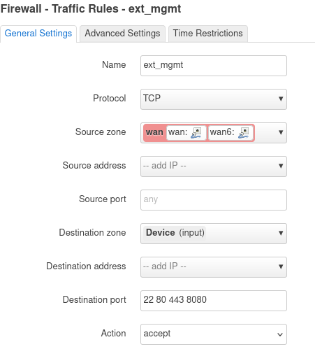
Click [Save] and then [Save & Apply] buttons. The firewall rule accepts packets from the WAN Zone to the the device (or Router).
While you are on the Router, make a note of your WAN IPv6 address (on the eth0 interface). Any of the addresses will work, so pick a short one. My Router has this address as a short address: fd10:a1ea:cafe:fd44::a61/128
We'll enter the address into the Lab DNS, so that you can just use a name (you did name your Router, right?) to get to your device.
Setting up VLANs on the Router from the WAN Port
Only do this section if managing the router from the WAN port!
Since OpenWrt can deal with VLANs, we'll setup the 4 router ports, with port 1 & 2 as normal br-lan ports, port 3 connected to VLAN 103, and port 4 connected to VLAN 104.
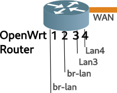
In the Lab will be using a 5 port OpenWrt router and configure the ports as per the following table:
| VID | Port | br-lan | LAN3 | LAN4 |
|---|---|---|---|---|
| 101 | 1 | U | ||
| 101 | 2 | U | ||
| 103 | 3 | U | ||
| 104 | 4 | U | ||
| None | WAN |
Connect your laptop to the upstream network of the router, and log into the web interface (LuCI) using the WAN IPv6 address you noted earlier. Navigate to the Network->Interfaces page, and select the Devices tab.
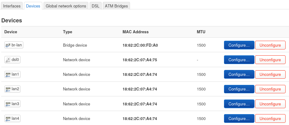
Then click on the blue Configure button for br-lan, and then click the Bridge VLAN Filtering tab. Enable VLAN Filtering and configure as per the able above. Make sure you select Is Primary VLAN for port 1.
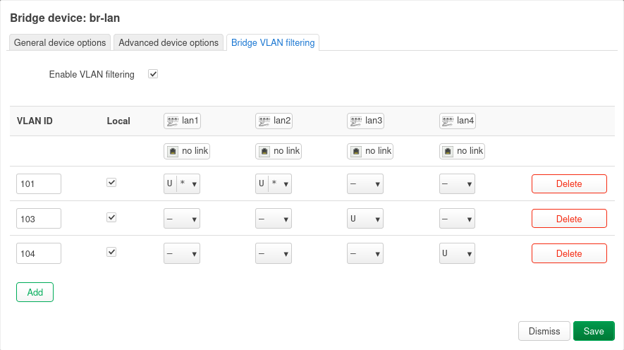
Click [Save], then [Save & Apply].
Doing the above will disconnect your laptop from the router!
Alternate Config of VLANs using the CLI from the LAN port
Skip this section if you already configured the router from the WAN port
You may not have the luxury of configuring the router VLANs from the WAN port. Should this be the case, you will need to ssh into the router, and manually edit the configuration files.
Change directory to the /etc/config and make a back up of the network file (hint: use cp). Then edit the network file.
Add/Edit the following in the network file, MAKE sure you select your IPv4 subnet to a unique number
config interface 'lan'
    option device 'br-lan.101'
    option proto 'static'
    option ipaddr '192.168.222.1' #<== set to unique subnet
    option netmask '255.255.255.0'
    option ip6assign '60'

config bridge-vlan
    option device 'br-lan'
    option vlan '101'
    list ports 'lan1:u*'
    list ports 'lan2:u*'

config bridge-vlan
    option device 'br-lan'
    option vlan '103'
    list ports 'lan3'

config bridge-vlan
    option device 'br-lan'
    option vlan '104'
    list ports 'lan4'
Then save the file, hold your breath, and restart networking /etc/init.d/network restart
Assigning subnets/prefixes to the VLANs
Now it is time to add Layer 3 interfaces to the new VLANs created (103 & 104).
Using LuCI and the Network->Interfaces->Interface tab, click [Add New Interface] button and create a Static interface, name it LAN3 and connect it to br-lan.103. Click [Create Interface]
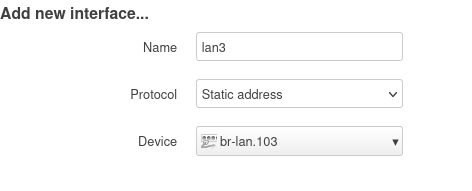
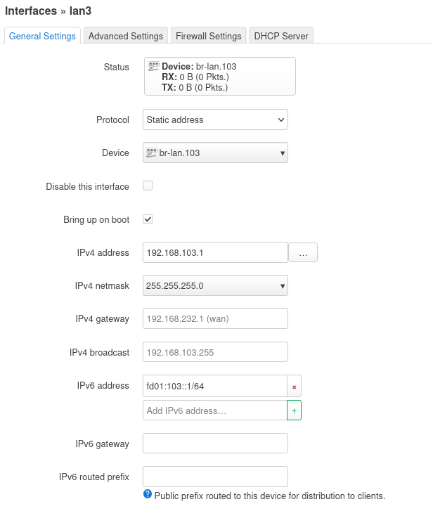
Then fill in the blanks as shown. Because IPv6 doesn't use NAT we'll change fd00 to something like fd9a or whatever your favourite 2 digit number is. This will create a unique IPv6 address in the lab network. Be sure to adjust the addresses to your network.
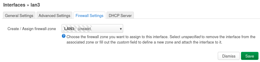
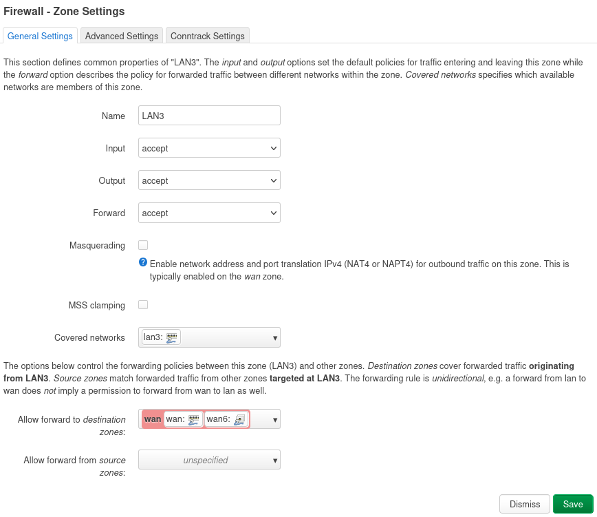
Then switch to the [Firewall Settings] tab and create a new Firewall Zone LAN3
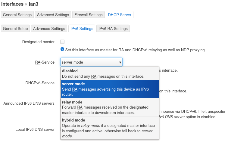
Then switch to the [DHCP Server] tab and click [Setup DHCP Server]
Then switch to the IPv6 Settings tab enable RA Service, by selecting [Server Mode], and click [Save].
Back at the LuCI Interfaces screen, click [Save & Apply].
Congratulations, you have configured the first VLAN as LAN3, now repeat for the next VLAN (LAN4), making adjustments for the static addressing (use 192.168.104.1 for LAN4, and so on. Additionally, don't forget to increment the IPv6 second Quatet to something like fd9a:104::1/64, keeping the address unique.
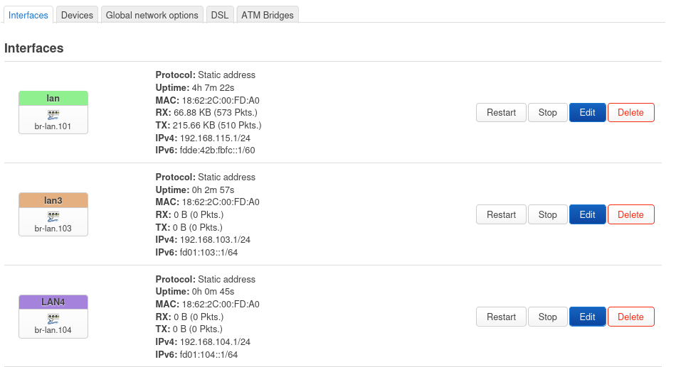
Lastly, click [Edit] on the LAN interface, and set the Device to br-lan.101. This will reconnect ports 1 & 2, to the layer 3 interface called "LAN".
The LuCI Interface screen should start to look like this:
Setting up some Firewall Zones for your new VLANs
So far, we have created some new internal VLANs, and assigned Layer 3 interfaces to them. Now it is time to setup some basic Firewall Rules for the new interfaces.
Use the following table to map interfaces to different Firewall Zones (later we can change the names of the zones)
| Zone | Purpose |
|---|---|
| LAN3 | Guest |
| LAN4 | DMZ |
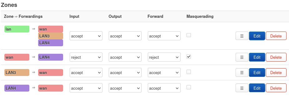
In LuCI, go to Network->Firewall, the zones (near the bottom of the page) should look something like this:
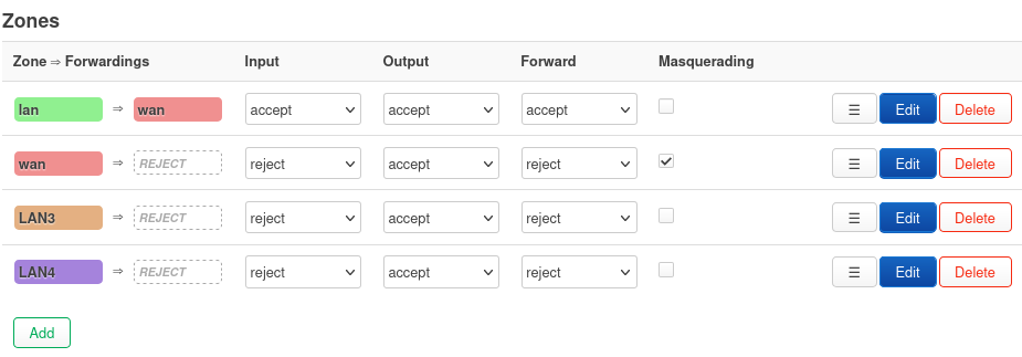
Setup the LAN3 zone to have outbound access to the internet, but not the other zones
Setup the LAN4 zone to have outbound and inbound access to the internet, but not the other zones
Lastly, setup the the green LAN zone to have access to the other zones (LAN3 & LAN4). When you are done the Firewall Zones should look like this:
Firewall still requires Rules
The Firewall Zone setup default policies on how the different zones will interact. However Firewall Rules still must be created to allow access from the WAN zone (default REJECT) into the DMZ (LAN4).
In the following example, we will setup internet access to port 80 devices in the DMZ (LAN4)
IPv6
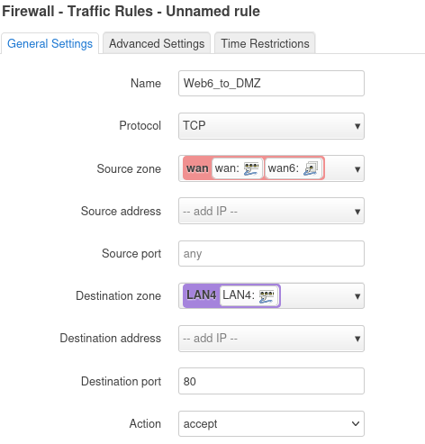
Configuring IPv6 is pretty straight forward, since no NAT is required. In Network->Firewall click the [Traffic Rules] tab, where you should see several rules already defined. Most of these are default to make IPv6 work correctly, don't delete them.
To add another rule for IPv6 port 80, scroll down and click [Add], after filling out the values, click [Save] and [Save and Apply].
IPv4
If we didn't have to deal with NAT, we'd be done. Alas, there is NAT, which requires port forwards
In the Network->Firewall page, click the Port Forwards tab, and click [Add]
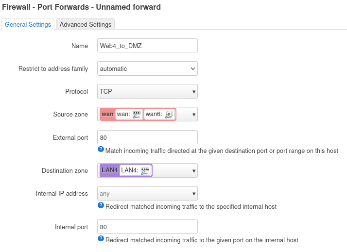
As you can see, in the Port Forward, we mapped inbound destination port 80 to internal port 80 (in the DMZ/LAN4 zone). This works fine for the first webserver, but because of NAT, it won't work for the second server, since both share the same external IPv4 address, and therefore they both can't listen on port 80. This is one of the reasons why NAT is evil.
There is an error in the IPv4 port 80 port forward.
Testing your VLAN Lab Network
Now it is time to test your VLAN configuration. The Second person, will connect to the LAN, LAN3 and LAN4 ports on the router and see what IPv4 and IPv6 addresses they get.
1. Hands On - Checking VLAN Connectivity and debugging
Attempt/Answer the following:
- Why is it tricky to reconfigure the LAN interface when connected to a LAN port? What happens if you try?
- Did you get the expected IP addresses when plugging into Ports 3 and 4?
- How many Firewall Zones have been configured?
- What Firewall Zone can only access the internet, but no other Zones? Why?
- There is an error in the IPv4 Port Forward Rule, what is it?
- Extra Credit: Why don't all the VLANs (lan, lan3, and lan4) have IPv6 GUA addresses?
Configuring a Guest Wifi Network
Now that we have all these cool interfaces, and firewall zones, let's put them to work.
In LuCI, Network->Wireless select the 5Ghz radio (802.11ac/n), if you have one. Click [Add] to the right of the radio. Fill out the info similar to the following (setting Wifi name to 'router name', channel to 'auto', width to '20' and Network to 'lan3':
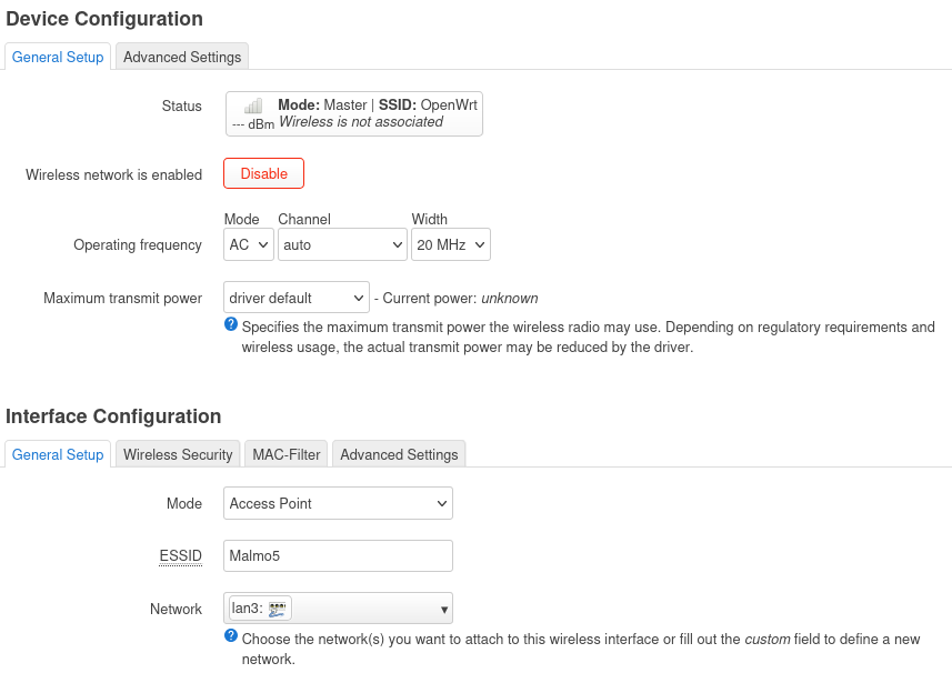
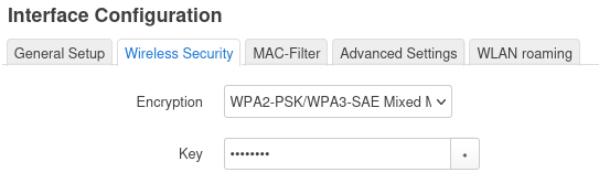
Click on the Wireless Security tab, and click 'WPA2-PSK/WPA3-SAE Mixed' which is the current strongest wireless security. Then assign a key or Wi-Fi password (minimum length of 8 chars)
Click [Save] and then [Save & Apply]
Done! Because we had previously setup VLANs and Firewall Zones, setting up the Guest Wifi is pretty easy.
OpenWrt is the Swiss Army Knife of Routers
There were a lot of steps to setup an additional Guest Network, and DMZ on the router. But there were also a lot of configuration which has very good defaults, which we didn't have to change.
It is best practice to have at least two networks at home. One where you want your data protected (the production network) and one where you may be placing IoT or other devices which may be phoning home or have weak security and become part of a bot net that you don't want attacking your stuff. This is the Guest Network.
OpenWrt router software enables the hobbyist to experiment with different configurations creating Wireless Mesh networks (802.11s) or simple wireless bridging (using WDS), or running routing protocols (RIPng or Babel), or just setting up a Guest network so your production network is protected from the rest of the world (and your guests).
Notes:
27 January 2025
updated 1 March 2025