NanoPi Router + VLANs
|
by Craig Miller
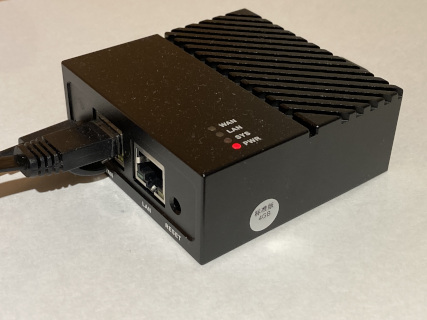
This is the second in the series covering the NanoPi as a high performance router running OpenWrt. It only has 2 GigE ports (WAN and LAN). It also has two (2) USB ports, which support wireless dongles, making it a wireless router as well. It has excellent performance, with 970 Mbits/sec of routing power.
See the Introducing the NanoPi article for an overview of the NanoPi.
VLANs solving problems
But what if the one LAN port is too limiting? What if you want to follow best practices and have at least one production LAN and one guest LAN?
One can use Virtual Local Area Networks (VLAN) and a managed switch to create multiple physical ports assigned to VLANs. By using a trunk port it is possible to carry multiple VLANs on a single physical port.
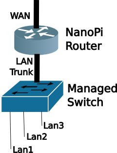
The Managed Switch then associates physical ports with specific VLAN IDs. The output of each physical port will be a single untagged subnet/prefix.
How do VLANs work
The V in VLAN is for Virtual. Through a method of IEEE 802.1Q tagging is is possible to segregate different subnets on the same wire.

Note the 802.1Q header (or VLAN tag) inserted between the Ethernet and the payload (which would include the IP header).
What is a VLAN tag?
The VLAN Tag is a four (4) byte header that is inserted just after the Ethernet Header.
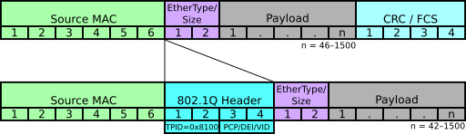
The first 2 bytes are the Tag Protocol ID (TPID) which identifies this header as 802.1Q (0x8100) . The Ethertype tells the protocol stack how to decode the data after the VLAN tag. Typically this would be 0x0800 or 0x86dd (for IPv4 or IPv6 respectively. IANA list of EtherType codes).
The second 2 bytes has 4 bits of bit fields, with the remaining 12 bits for the VLAN ID (VID). 212=4096 Because programmers start counting from zero, the range of VIDs is 0-4095.
Why a managed switch?
First, let's describe an unmanaged switch. Which a relatively dumb switch, which just forwards packets based on the destination Ethernet Media Access Control (MAC) address. Back in the day this type of switch was called a learning bridge as it would learn the MAC addresses associated with the physical ports, building a Layer 2 forwarding table. If the destination MAC address is not found in the forwarding table, then the switch floods the packet out all ports (except the ingress port).
A Managed Switch gives the network admin more control over the flow of packets. Typically the managed switch not only creates a L2 forwarding table based on MAC addresses, but it also understands the 802.1Q VLAN header. The network administrator can associate physical ports with VIDs via configuration. The Managed Switch has the ability to add/drop VLAN tags from the frame.
The advantage of the add/drop functionality is that the Ethernet devices connected to the switch don't have to deal with VLAN tags. As the frame egresses the managed switch, it strips off the VLAN tag, and the end device only sees a regular (or untagged) Ethernet frame. We'll use this feature in our lab.
Preconfigured Managed Switch
We will be using another OpenWrt router to act as our Managed Switch. Since OpenWrt can deal with VLANs, and the embedded Ethernet Switch (typically ports 1-4) can add/drop VLAN tags. It also has the benefit that the switch is managed via IPv4 and IPv6.
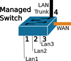
In the Lab will be using a 5 port OpenWrt router as the Managed Switch. The ports have been preconfigured for the following:
| VID | Port | LAN1 | LAN2 | LAN3 |
|---|---|---|---|---|
| 101 | 1 | U | ||
| 102 | 2 | U | ||
| 103 | 3 | U | ||
| All | 4 | T | T | T |
| None | WAN |
We'll use ports 1,2,3 for our breakout LAN ports associated with LAN1, LAN2, LAN3 respectively. Port 4 is configured for the Trunk port. This will connect to the LAN port on the NanoPI. The last port, the WAN port will not be used in the LAB.
Choosing ports on the Managed Switch
Since it is a managed switch, the network administrator can choose to map any port to any VLAN. But it is also a good idea to keep it simple. In this lab, we can configure up to 3 VLANs on the NanoPi, and have those virtual connections flow down to ports 1,2, and 3. Initially, I used VIDs 1-3 as well, but some of the OpenWrt routers use VIDs 1 & 2 for their own internal use, hence the VIDS 101, 102, and 103.
I chose to keep the WAN port as a WAN port, as it is already configured to be a DHCPv4 & DHCPv6 client, which means it will get an address automagically. If I re-assigned the WAN port to a fifth LAN port, then I would have to assign a static IP address to manage the switch. As soon as I move the switch to another LAN, the statically assigned address would be in the wrong subnet, and would be unreachable. Leaving the WAN port a WAN port just makes things easier in the long run.
Setting up the NanoPi for the Lab
Again to make things easier, we'll configure the NanoPI via the WAN interface. However, there are default firewall rules which prevent this. Clearly, good security does not suggest opening up the NanoPi management to the internet. But since we are on an internal LAN, we can be more permissive on the firewall rules.
We'll add a firewall rule with the following steps:
- Connect your laptop to the NanoPI LAN port
sshinto your Nano Pi, and append the following to the /etc/config/firewall file:
config rule
option dest_port '22 80 443 8080'
option src 'wan'
option name 'ext_mgmt'
option family 'ipv6'
option target 'ACCEPT'
list proto 'tcp'
- Restart the firewall with the
fw4 reloadcommand
Or you can use LuCI web interface: Network->Firewall->Traffic Rules Tab->Green Add button
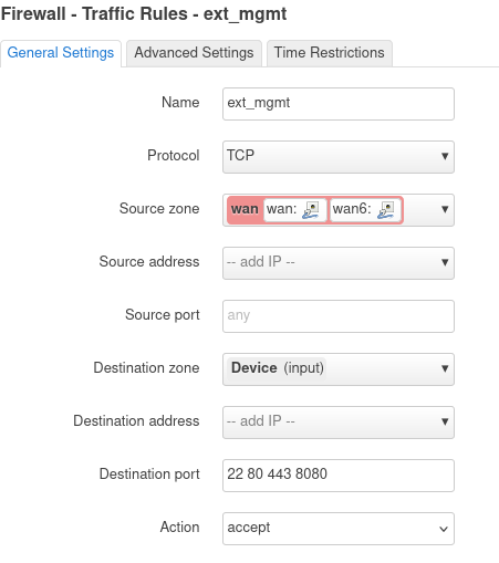
Click [Save] and then [Save & Apply] buttons. The firewall rule accepts packets from the WAN Zone to the the device (or NanoPi).
While you are on the NanoPi, make a note of your WAN IPv6 address (on the eth0 interface). Any of the addresses will work, so pick a short one. My NanoPi has this address as a short address: fd10:a1ea:cafe:fd44::b48/128
We'll enter the address into the Lab DNS, so that you can just use a name (you did name your NanoPi, right?) to get to your device.
Lastly, but not least, connect your Laptop to the Lab Network (the unmanaged Ethernet Switch, or to the Lab Wireless), as we will do the remaining configuration via the WAN port on your NanoPI.
NanoPi + VLANs Lab Setup and Backup Config
For the Lab, we will pair up, sharing one NanoPi and one Managed Switch. The Network Admin will connect to the Lab Network, and the Network Tester will connect to one of the ports (1,2,3) of the Managed switch.
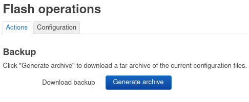
Before making large configuration changes to your OpenWrt router, it is good practice to back up the config. This is easily done in LuCI: System->Backup/Flash Firmware. Click [Generate Archive]]
Configuring the NanoPi for VLANs
Using your laptop connected to Lab Network, we will first configure the br-lan device via the web interface (LuCI) Network->Interfaces->Devices Tab

Click on [Configure] for the br-lan, then click on [Bridge VLAN Filtering]
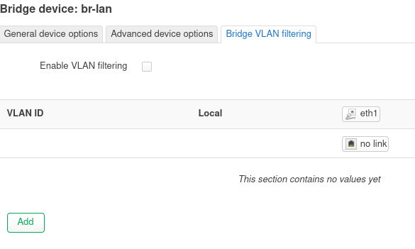
Then we will check the box "Enable VLAN filtering", and then click the green [Add] button. Adjust the VID to 101 and change the type to "Tagged". Repeatedly click [Add] to add VIDs 102 and 103, ensuring they are also tagged. After 3 VLANs have been added, click [Save], then click [Save & Apply]
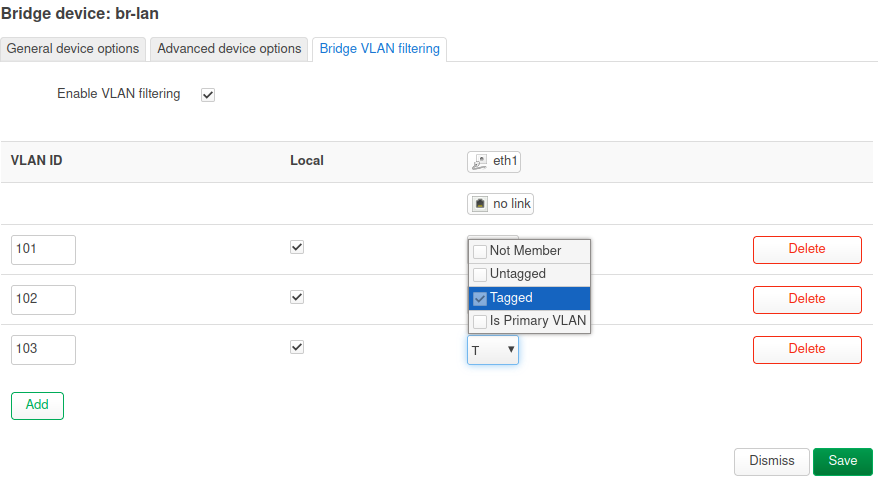
At this point you will not be able to managed the NanoPi from the LAN interface, since it is only expecting tagged Ethernet frames (for course, it is possible to create a tagged interface on your Linux laptop, and regain connectivity if needed, but that configuration is out of scope for this lab).
Assigning subnets/prefixes to the VLANs
Using LuCI and the Network->Interfaces->Interface tab, click [Add New Interface] button and create a Static interface, name it LAN1 and connect it to br-lan.101. Click [Create Interface]
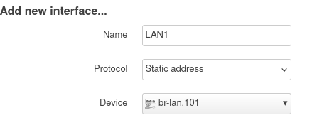
Then fill in the blanks as shown. Because IPv6 doesn't use NAT we'll change fd00 to something like fd9a or whatever your favourite 2 digit number is. This will create a unique IPv6 address in the lab network. Be sure to adjust the addresses to your network.
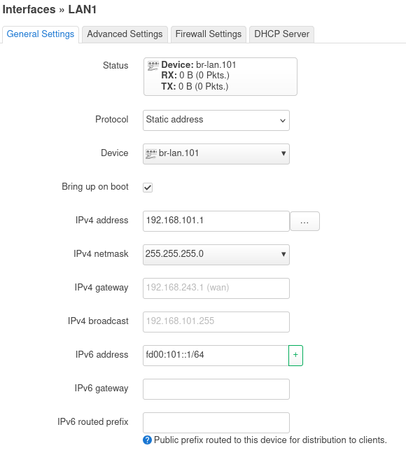
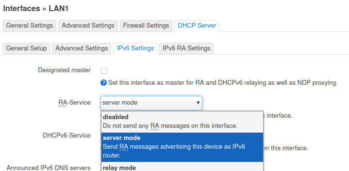
Then switch to the [DHCP Server] tab and click [Setup DHCP Server]
Then switch to the IPv6 Settings tab enable RA Service, by selecting [Server Mode], and click [Save].
Back at the LuCI Interfaces screen, click [Save & Apply].
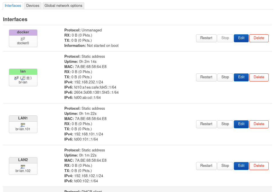
Congratulations, you have configured the first VLAN as LAN1, now repeat for LAN2 and LAN3, making adjustments for the static addressing (use 192.168.102.1 for LAN2, and so on. Additionally, don't forget to increment the IPv6 second Quatet to something like fd9a:102::1/64, keeping the address unique.
The LuCI Interface screen should start to look like this:
Creating your VLAN Lab Network
Now that you have the NanoPI configured, connect up the NanoPI LAN port to port 4 on the "managed switch", which has been preconfigured to catch VIDs 101, 102, and 103.
Now it is time to test your VLAN configuration. The Second person, will connect to the Managed Switch port 1 (with Ethernet) and see what IPv4 and IPv6 addresses they get.
1. Hands On - Checking VLAN Connectivity and debugging
Using the Wireshark remote capture method, capture the conversation as the Tester connects to one of the ports on the Managed Switch. The Network Admin will run the Wireshark remote capture, capturing on the NanoPi br-lan interface and:
Attempt/Answer the following:
- What is the IP address did the Tester receive when connecting to the Managed Switch Port 1?
- What is the IP address did the Tester receive when connecting to the Managed Switch Port 2?
- Are the above addresses different? Why?
- Did Wireshark pick up the DHCPv4 and IPv6 conversations? Were they tagged?
- Extra Credit: Why can't the Tester see the VLAN tags (assuming they sniffed their Ethernet interface)?
More about VLANs
As you can see, VLANs are useful for combining multiple subnet/prefix networks onto a single wire. But what about security?
No, VLANs add no security, as the 802.1Q tag is in the clear, and a wireshark will display the VIDs on the wire. As mentioned earlier, it is possible to configure a VLAN interface on a linux laptop, then it could join one of Virtual LANs on the wire.
One LAN port a limitation?
It doesn't have to be. As you have seen in this session, we can create multiple VLANs on the NanoPi LAN port, and fan them out to individual ports using a managed switch.
It is best practice to have at least two networks at home. One where you want your data protected (the production network) and one where you may be placing IoT or other devices which may be phoning home or have weak security and become part of a bot net that you don't want attacking your stuff. This is the Guest Network.
Now with VLANs, you can have as many networks as you want (up to 4095) with your NanoPi. The NanoPi is not only a cute little headless device, but it is also a high performance router with the ability to create multiple VLANs.
Notes:
14 Oct 2024