Creating a Cantenna
or
WLAN Fun in the Home
Two of my favorite geeky things are computer networking and radio
transmission (RF). Mixing the two has been a passion of mine, dating back
to the 80's when as Chief Engineer of Hawaii Public Radio, we put stock
quote data on a sub carrier of KHPR. Making a Wireless LAN antenna just
for the fun of it, has held a great attraction to me, since it combined
my two favorite geeky things.
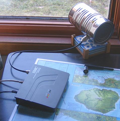
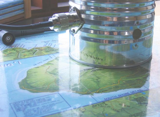
WLAN Access Point connected to my Cantenna pointing out the window
The Experiment
There are a plethora of how-to's on the internet explaining how to make a cantenna, and studying the different web pages will give you a variety of conflicting suggestions as to the dimensions one should use. So given that there are no "right" answers, it is an excellent opportunity to experiment.First one needs a wireless access point, or router with an removable external antenna. Routers and Access Points (AP) are different, but for the purposes of the cantenna, both work just fine. Second, one needs a "pig tail" which is just a short piece of coax with a non-standard connector to connect to the AP, and a standard connector, such as a Type N. My SMC AP uses a reverse TNC connector for the non-standard output.
I have heard that the FCC has mandated that WLAN vendors use non-standard connectors just to thwart folks who want to have a little RF fun. Given that WLAN uses an unlicensed band which is shared by cordless telephones, Microwave ovens and Blue Tooth communications gear, it probably isn't a bad thing to limit interfering with your neighbor's wireless everything.
Fortunately, if you lack the soldering skills or access to the non-standard connectors, pre-made pigtails can be mail ordered. I purchased mine from JEFA, and it arrived in just a couple of days.
The rest of what is required is pretty simple, just a Type N female chassis mount connector, a little wire, and a can! Then the fun can begin!
As I said there are many websites which will give guidance on where to position the Type N connector on the can. I found the following to be pretty useful:
Of course, I little knowledge of RF is always good, but not absolutely required. The key ingredients to creating your own cantenna are the radiator, and the can. The radiator is just a short piece of wire soldered to the end of the Type N female connector. This 31 mm long wire sticks into the can via a hole conveniently cut into the side. the radiator does all the work of sending the RF signals into the air. Since the is a direct relationship between frequency and wavelength, the length of the wire is pretty specific. Where the radiator is placed in the can seems be much more flexible.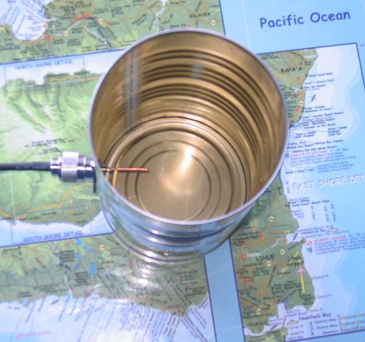
Looking down into the cantenna -- note the 31 mm radiator (wire)
sticking into the can
Measuring Success
Lastly one needs to have some method of measuring success. I use a linux program called wavemon which runs in a terminal window. A key advanage of Wavemon is that it provides signal strength measurements down to the db rather than providing the usual 5 bars on the task bar, thus affording much more granularity in measurement.
Wavemon in action
A key advantage of using wavemon was that I could remotely log into my laptop, which was the test receiver, and display wavemon on another closer computer I had located near the AP. Thereby getting real-time feedback as I moved the cantenna right and left, quickly getting an idea of the radiation pattern.
An Antenna Pattern provided by a commercial manufacturer
I didn't take the time to create any fancy antenna patterns, but I did notice that turning the cantenna to the right and left would sometimes increase the signal rather than decrease it. I especially noticed this when I mounted the radiator close the bottom of the can (34 mm).
Hole at 34 mm which had a cartiod radiation pattern
Another website had recommended a radiator insertion point higher up
on the can (50 mm). Using my Makita cordless drill made moving the insertion
point a breeze. I found the 50 mm insertion point to have a better pattern.
The Numbers
I performed both indoor and outdoor tests. The indoor test range was shorter and consisted of a distance of about 22 ft (7m) separated by three woodframed dry-wall walls (standard house construction). The outside range was a distance of 75 ft (23m) and had no obstructions (besides a leafless tree, and a window).| Interior Range (7 m) | Signal | Noise | Signal/Noise |
| Reference Antenna | -68 | -96 | +28 |
| Tomato Cantenna (85 mm diameter, feed@62mm) | -59 | -95 | +36 |
| Juice Cantenna (107 mm diameter , feed@50mm) | -58 | -98 | +40 |
| Exterior Range (23 m) | Signal | Noise | Signal/Noise |
| Reference Antenna | -67 | -96 | +29 |
| Juice Cantenna (107 mm diameter , feed@34mm) | -59 | -95 | +36 |
| Juice Cantenna (107 mm diameter , feed@50mm) | -58 | -98 | +40 |
Conclusions
What have a learned from this fun? It is pretty easy to make an antenna which provides 10db gain (10x power) over the included "rubber ducky" antenna. My juice cantenna actually has about 12db gain over the rubber ducky antenna. The Cantenna is a true directional antenna with a front to back ratio of 20 db, meaning the signal radiated out the back of the antenna is about 8db less than that of my reference antenna.Once one gets past the hard to get non-standard connector on the back
of the AP/Router, experiementing with a Cantenna is not only fun, but the
pineapple juice was tasty as well!
28 March 2004